
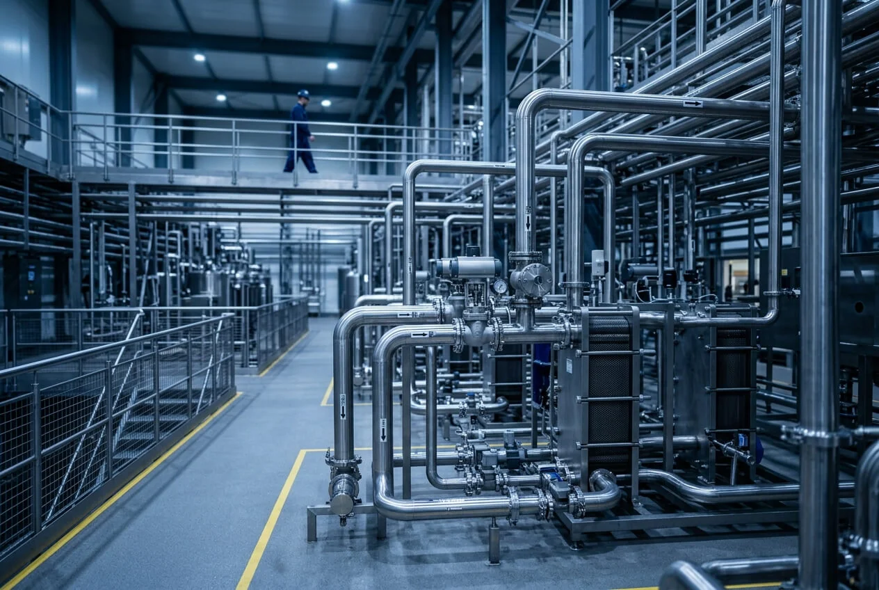
LKH Centrifugal Pump
LKH centrifugal-pump spares support sealing, hydraulic performance and reliable operation. Prioritise the shaft seal and elastomers for routine planning; assess impellers and shafts against their actual condition and the pump configuration.
Shaft seal assembly
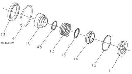
Position labels correspond to the component listing.
| Pos. | Component | Selection notes |
|---|---|---|
| 11 | Stationary seal ring | Silicon-carbide stationary face |
| 12 | Stationary seal O-ring | Elastomer sealing the stationary face |
| 13 | Seal spring | Maintains seal-face contact |
| 14 | Rotating seal ring | Carbon or silicon carbide, according to duty |
| 15 | Rotating seal O-ring | Confirm against the installed arrangement |
| 10 | Drive ring | Single or flushed seal configuration |
| 44 | Seal-housing O-ring | For the applicable flushed arrangement |
| 45 | Lip seal | For the applicable flushed arrangement |
Single and flushed seal arrangements differ. Confirm seal faces, elastomers and installed configuration before selection.
Ask DFT about thisPump casing and impeller
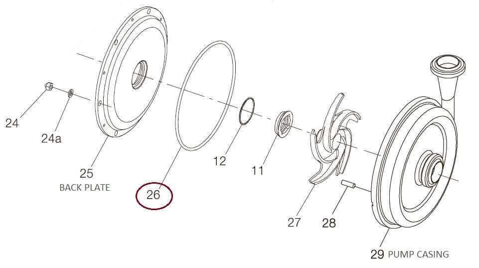
Position labels correspond to the component listing.
| Pos. | Component | Selection notes |
|---|---|---|
| 26 | Casing joint ring | Match pump size and elastomer |
| 27 | Impeller | Confirm pump model, diameter and duty |
| 28 | Impeller screw | Verify against the installed assembly |
The joint ring depends on pump size. Impeller diameter may be trimmed for the installed flow and head; identify it using the pump serial number.
Ask DFT about thisPump shaft
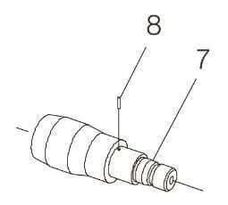
Position labels correspond to the component listing.
| Pos. | Component | Selection notes |
|---|---|---|
| 7 | Pump shaft | Match motor size and shaft connection |
| 8 | Shaft pin | Confirm the corresponding shaft assembly |
The shaft depends on the motor and pump configuration. Provide the motor rating and nameplate details.
Ask DFT about thisSelection & service guidance
Shaft seals and O-rings
The seal assembly includes stationary and rotating faces, a spring and associated O-rings. Face materials and elastomers must suit the product, cleaning chemicals and temperature. Confirm whether the installed arrangement is single, flushed or double mechanical. During seal repair, assess the mating faces together and confirm the appropriate complete seal assembly with DFT.
Casing joint rings
The casing joint ring seals the pump cover to the casing. Match it to the pump size and elastomer specification. Keep suitable replacements available for planned opening and replace damaged, flattened or swollen rings in accordance with the equipment manual.
Impellers and shafts
Impeller diameter can be trimmed to meet a particular flow and head, so a standard maximum-diameter impeller may not match the installed duty. Shaft selection also depends on the motor and mechanical configuration. Share the pump serial number and motor details before requesting either component.
What to send DFT
Provide the pump model and serial number, motor rating, seal arrangement, process fluid, operating temperature and cleaning conditions. Describe where leakage or wear occurs and the quantity required. Nameplate and component photographs can be shared through an agreed contact channel.
Service planning
Consider shaft-seal assemblies, seal O-rings and casing rings for critical-spares stock. Repeated seal trouble warrants checks for dry running, loss of flush, cavitation or misalignment. Isolate and depressurise the pump before maintenance; follow the model-specific manual and use competent service personnel.