
Planning a hygienic valve automation retrofit
Check the valve, actuator and controls together before selecting a control top or promising additional functionality.
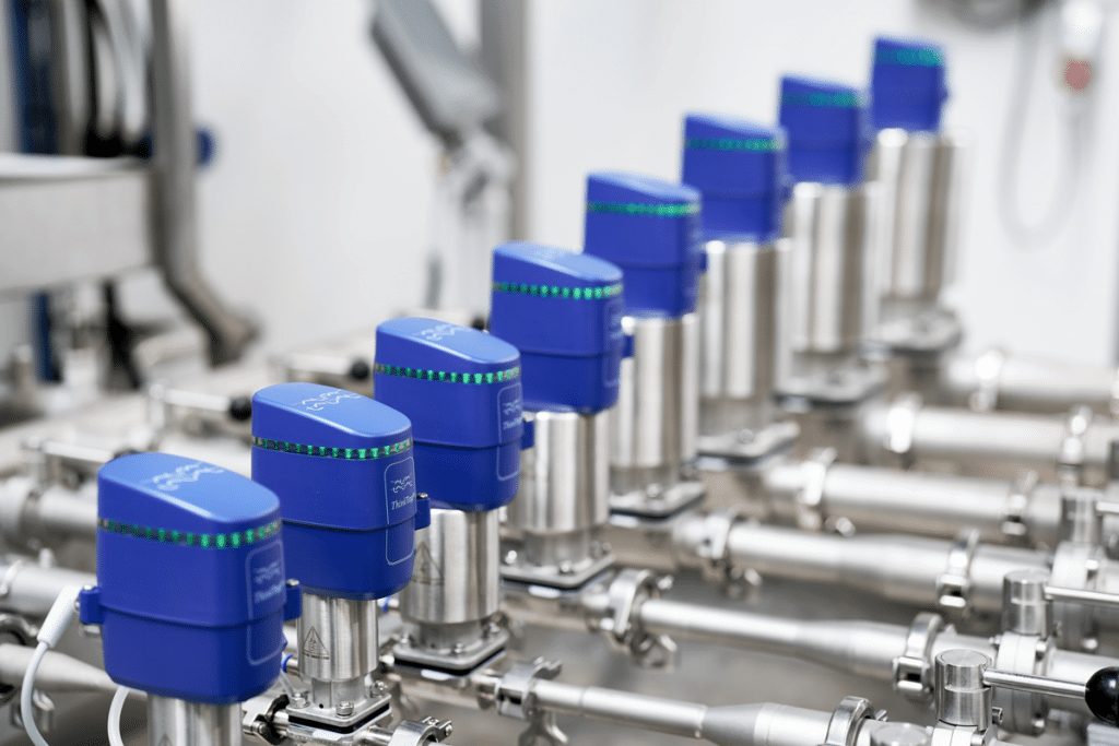
A control-top retrofit can improve valve operation and feedback, but compatibility depends on the installed valve and the required functions. Define the process behaviour first, then select and test the complete arrangement.
Identify exactly what is installed
Begin with the valve model, size, serial details, actuator type and current feedback arrangement. A manual valve does not become an automated assembly simply by adding a control head. The complete mechanical and pneumatic configuration must support the intended operation.
Create a valve list linked to the process diagram. For each item, record whether the requirement is indication only, remote on/off operation or another documented function. Note the existing power supply, available instrument air and control-system interface. Photographs are useful for identification, but they should accompany model information rather than replace it.
Match the control unit to the function
Alfa Laval describes ThinkTop units that monitor valve position and operate pneumatic valves through solenoid control. The V50 product page identifies particular valve families and configurations. Other versions offer different functions and interfaces, so selection should use the current documentation for the exact product.
Do not assume that every control top supports every valve or cleaning action. A seat-cleaning function depends on the valve design, control-unit configuration and the commissioned sequence. Similarly, diagnostic information is useful only when the receiving system is configured to interpret and present it appropriately.
Define how the operator will use feedback
Write down what the control system should do if the commanded position is not confirmed within the expected time. Consider startup, recipe change, cleaning and loss of utilities as separate operating situations. Position feedback reports a detected mechanical condition; it does not by itself prove cleanliness or leak-tight isolation.
An engineering review should identify which indications belong on the operator display, which events require alarms and which actions require an interlock. Avoid adding numerous notifications without clear ownership. Each message should help an operator recognise the condition and follow an agreed response.
Plan acceptance before installation
Agree a test matrix before the shutdown. It should cover the specified positions, loss and restoration of utilities, relevant alarms and communication with the control system. Where cleaning functions are involved, the process owner should define acceptance criteria and the required validation evidence.
Keep the final configuration, approved drawings and spare-part identification with the equipment record. For a retrofit enquiry, send the valve list, interface requirements, available utilities and desired operating sequence. DFT can support the selection discussion and technical coordination; compatibility and commissioning requirements must be confirmed for the actual assembly. Any claimed reduction in cleaning consumption needs application-specific evidence, not an assumption taken from a different installation.
Further reading
Discuss your application
Share your process conditions and equipment requirements with Delta Flow Tech.
Ask DFT about thisContinue reading
Why a plate heat exchanger misses its target temperature
Separate a changing process duty from fouling or a flow problem before deciding that the exchanger needs more plates.
Learn moreSteam traps: selecting the duty and planning a useful survey
Assess the complete condensate path, then use a consistent survey to distinguish normal operation from leakage or restricted drainage.
Learn more